CATEGORIES:
BiologyChemistryConstructionCultureEcologyEconomyElectronicsFinanceGeographyHistoryInformaticsLawMathematicsMechanicsMedicineOtherPedagogyPhilosophyPhysicsPolicyPsychologySociologySportTourism
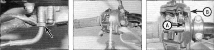
Cable bracket screw (A), inner cable nipple (B) and choke linkage lever (C)lever (see illustration).Withdraw the cable from the machine noting the correct routing. 3 Unscrew the cable elbow nut from the left handlebar switch housing (see illustration).Remove the handlebar switch housing screws and separate the two halves of the switch to gain access to the cable nipple (see illustration). 4Detach the nipple from the pulley and withdraw the cable from the housing (see illustration). Installation 5 Fit the choke cable elbow into the socket in the left handlebar switch housing and tighten the nut. Lubricate the cable nipple with multipurpose grease and install it in the pulley. 6 Fit the two halves of the switch housing together, install the housing screws and tighten them securely. Ensure the lever turns freely. 7 Feed the cable through to the carburettors, making sure it is correctly routed. The cable must not interfere with any other component and should not be kinked or bent sharply. 8 Lubricate the cable nipple with multipurpose grease and attach it to the choke linkage lever then fit the outer cable into its bracket, making sure there is a small amount of freeplay in the inner cable, and tighten the bracket screw (see illustration 11.2). 9Check the operation of the choke cable (see Chapter 1). 10Install the fuel tank (see Section 2).
A Choke cable elbow nut (arrowed) B Remove the screws and split the switch housing 11.4 Choke cable nipple attachment point (A) and pulley/lever (B) Fuel and exhaust systems4*13
U-shaped bracket (A) locates on frame tube (B) Route the breather hose behind the engine unit Remove tubes from bracket (arrowed)
12 Air filter housing- §j removal and installation ^ Removal 1Remove the fuel tank (see Section 2), and the carburettors (see Section 6). 2 Remove the bolts securing the air filter cover to the filter housing and remove the cover and the filter element (see Chapter 1). 3 Release the hoses from the guides on the upper right-hand side of the filter housing. Release the drain hose from the bracket on the back of the exhaust system and pull the filter housing forward to release the U-shaped mounting bracket below the intake duct from the frame tube (see illustration). 4Lift the housing out of the frame between the top frame tubes. Release the clip securing the breather hose to the filter housing and detach the hose. Installation 5 Installation is the reverse of removal. Check the condition of the breather hose(s) and drain hose and renew them if necessary. 6 Route the breather hose behind the engine unit before installing the filter housing (see illustration). 7Make sure the mounting bracket locates correctly on the frame tube (see illustration 12.3).If the bracket is damaged, it can be replaced as a separate item from the filter housing. 13 Exhaust system- removal and installation |k
Warning: If the engine has been running the exhaust system will be very hot. Allow the system to cool before carrying out any work. Note: The exhaust system can be removed as a complete assembly. The silencer and downpipe assembly can be separated if required, but this is best done after the complete system has been removed, rather than doing it in situ. Removal
1 Remove the drain and breather tubes from the bracket on the back of the exhaust system below the engine unit (see illustration).
2Unscrew the nuts securing the downpipes to the cylinder head (see illustration). 3Unscrew the nut and remove the washer and bolt securing the exhaust pipe to the frame bracket (see illustrations). 4Unscrew the nut that secures the silencer to the frame and remove the washer, but leave the bolt in place (see illustration).Support the system, then withdraw the bolt and manoeuvre the downpipes away from the cylinder head. 5 Remove the gaskets from the exhaust ports and discard them as new ones must be used (see illustration). 6 Ifrequired, remove the clamp to separate the silencer from the exhaust pipe. Discard the joint gasket as a new one must be used.
13.3b... and remove the bolt Date: 2016-01-14; view: 544
|