CATEGORIES:
BiologyChemistryConstructionCultureEcologyEconomyElectronicsFinanceGeographyHistoryInformaticsLawMathematicsMechanicsMedicineOtherPedagogyPhilosophyPhysicsPolicyPsychologySociologySportTourism
Oil clearance check
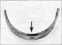
12The connecting rod bearing oil clearance should be checked before the engine is reassembled, even if the bearing shells and the crankpin journals show no apparent sign of wear. Bearing oil clearance is measured with a product called Plastigauge. 13Clean the backs of the bearing shells, the bearing locations in both the connecting rod and cap, and the crankpin journals with a suitable solvent or brake system cleaner. Press the bearing shells into their locations, ensuring that the tab on each shell engages the notch in the connecting rod/cap (see illustration).Clean the bearing surfaces with solvent, taking care not to touch any bearing surface with your fingers. 14 Cut an appropriate size length of Plastigauge (it should be slightly shorter than the width of the crankpin). Place a strand of Plastigauge on a cleaned crankpin journal. Do not place Plastigauge over the oil holes in the crankpins. Fit the cleaned connecting rod, shells and cap. Make sure the cap is fitted the correct way round so the previously made markings align and that the rod is facing the right way (see Step 3). Tighten the cap nuts evenly, in two or three stages, to the torque setting specified at the beginning of this Chapter, whilst ensuring that the connecting rod does not rotate on the crankshaft. Slacken the cap nuts and remove the connecting rod, again taking great care not to rotate the crankshaft. 15Compare the width of the crushed Plastigauge on the crankpin journal to the scale printed on the Plastigauge envelope to obtain the connecting rod bearing oil clearance (see illustration 25.17).Compare the reading to the specifications at the beginning of this Chapter. If the oil clearance falls within the specified range and the bearings are in perfect condition, they can be reused. 16 Carefully clean away all traces of the Plastigauge from the crankpin journal and bearing shells using a fingernail or other object which will not score the bearing surfaces. 17If the clearance is beyond the service limit, measure the diameter of the crankpin journal with amicrometer and compare the result with the appropriate figure in the table for connecting rod bearing shell selection. For example, if the journal being measured is code B, the table indicates that the service limit for that journal is 35.988 mm. If the journal diameter is larger than the service limit, new bearing shells can be fitted (see Steps 20 and 21). If the journal diameter is smaller than the service limit, the crankshaft should be renewed, although seek the advice of a Honda dealer or engineer to explore all alternatives. 18 Repeat the oil clearance check for the remaining connecting rod. Always renew all of the shells (on both connecting rods) at the same time. 19 Install the new shells and check the oil clearance once again. Date: 2016-01-14; view: 561
|