CATEGORIES:
BiologyChemistryConstructionCultureEcologyEconomyElectronicsFinanceGeographyHistoryInformaticsLawMathematicsMechanicsMedicineOtherPedagogyPhilosophyPhysicsPolicyPsychologySociologySportTourism
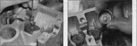
Check clearances on No. 2 cylinder valves with cam sprockets in this position26.12a Remove the follower. Every 16,000 miles 1.21
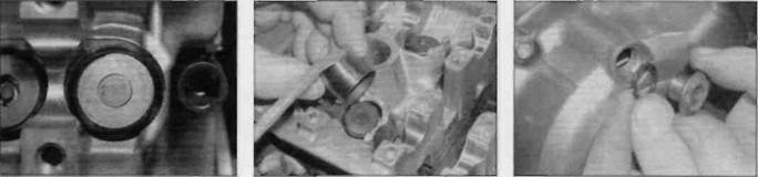
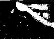
26.12b ... then retrieve the shim from the top of the valve ... 26.12c ... or inside the follower 26.13a Theshim size should be marked on its face ...
inside of the follower or pick it out of the top of the valve, using either a magnet or a small screwdriver with a dab of grease on it (the shim will stick to the grease) (see illustrations). Do not allow the shim to fall into the engine. 13 The shim size should be stamped on its face. However, it is recommended that the shim is measured to check that it has not worn (see illustrations). The size marking is in the form of a three figure number, eg 205 indicating that the shim is 2.05 mm thick. The new shim thickness required can then be calculated as follows. Note:Always aim to get the clearance at the mid-point of the specified range. 14 If the valve clearance is less than specified, subtract the measured clearance from the specified clearance then deduct the result from the original shim thickness. For example: Sample calculation - inlet valveclearance too small Measured clearance: 0.08 mm Specified clearance: 0.17 mm (0.16 to 0.18 mm) Difference: 0.09 mm Shim thickness fitted: 2.475 mm Correct shim thickness required is 2.475 - 0.09 = 2.385 mm 15 If the valve clearance is greater than result to the thickness of the original shim. For example: Sample calculation - exhaustvalve clearance toolarge Measured clearance: 0.35 mm Specified clearance: 0.26 mm (0.25 to 0.27 mm) Difference: 0.09 mm Shim thickness fitted: 1.975 mm Correct shim thickness required is 1.975+ 0.09 = 2.065 mm 16 Obtain the correct thickness shims from a Honda dealer. Where the required thickness is not equal to the available shim thickness, round off the measurement to the nearest available size. Shims are available in 0.025 mm increments from 1.200 mm to 2.900 mm. Note:If the required replacement shim is greater than 2.900 mm (the largest available), the valve is probably not seating correctly due to a build-up of carbon deposits and should be checked and cleaned or resurfaced as required (see Chapter 2). 17 When replacing a shim, lubricate it with molybdenum disuiphide oil (a 50/50 mixture of molybdenum disuiphide grease and engine oil) and fit it into its recess on the top of the valve, with the size marking facing up (see illustration). Check that the shim is correctly seated, then lubricate the follower with molybdenum disuiphide oil and install it onto the valve (see illustration). Repeat the
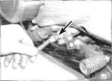
26.13b ... but measure it anyway process for any other valves until all the clearances are correct. 18 Install the camshafts (see Chapter 2). Rotate the engine several turns to seat the new shim(s), then check the clearances again. 19 Install all disturbed components in a reverse of the removal sequence. Use new O-rings on the alternator cover centre plug and the timing inspection plug. Smear the O-rings lightly with grease before fitting (see illustration).
1 Remove the old spark plugs as described in Section 13 and install new ones.
26.17a Fit the valve shim with its size marking facing up ... 26.17b . then lubricate and install the follower 26.19 Fit new O-rings onto the plugs 1.22 Routine maintenance and servicing Every 24,000 miles (36,000 km) or three years_________ Carry out all the items under the 4000 mile (6000 km), 8000 mile (12,000 km) and 12,000 mile (18,000 km) checks, plus the following:
28 Cooling system- draining,
Warning: Allow the engine to cool completely before performing this maintenance operation. Also, don't allow antifreeze to come into contact with your skin or the painted surfaces of the motorcycle. Rinse off spills immediately with plenty of water. Antifreeze is highly toxic if ingested. Never leave antifreeze lying around in an open container or in puddles on the floor; children and pets are attracted by its sweet smell and may drink it. Check with local authorities (councils) about disposing of antifreeze. Many communities have collection centres which will see that antifreeze is disposed of safely. Antifreeze is also combustible,so don't store it near open flames. Draining
1 Remove the fuel tank (see Chapter 4). Remove the pressure cap by turning it anticlockwise until it reaches a stop. If you hear a hissing sound (indicating there is still pressure in the system), wait until it stops. Now press down on the cap and continue turning until it can be removed (see illustration 10.7).
2Position a suitable large container beneath the water pump on the left-hand side of the engine. Remove the coolant drain plug and its sealing washer and allow the coolant to completely drain from the system (see illustrations).Retain the old sealing washer for use during flushing. 3 Position the container beneath the reservoir tank. Open the reservoir tank filler cap (see Daily (pre-ride) checks), detach the overflow hose from the bottom of the tank and drain the tank (see Illustration). Flushing
4 Flush the cooling system with clean tap water by inserting a garden hose in the pressure cap filler neck. Allow the water to run through the system until it is clear and flows cleanly out of the drain hole. If the drain hole appears to be clogged with sediment, remove the water pump cover and clean the pump (see Chapter 3). If the radiator is extremely corroded, remove it (see Chapter 3) and have it cleaned at a radiator shop. Flush the reservoir tank with clean water, then connect the overflow hose to the tank and fill the tank with clean water. 5 Install the coolant drain plug using the old sealing washer. 6 Fill the cooling system with clean water mixed with a flushing compound. Make sure the flushing compound is compatible with aluminium components and follow the manufacturer's instructions carefully. Fit the pressure cap and install the fuel tank (see Chapter 4). 7 Start the engine and allow it to reach normal operating temperature. Let it run for about ten minutes. 8 Stop the engine and let it cool. Remove the fuel tank, then cover the pressure cap with a heavy rag and turn it anti-clockwise to the first stop, releasing any pressure that may be present in the system. Once the hissing stops, push down on the cap and remove it completely. 9 Remove the coolant drain plug and drain the system once again. 10Fill the system with clean water and Refilling 11Fit a new sealing washer onto the drain plug and tighten it securely. Drain the reservoir tank and ensure that the hose clip is correctly installed when the overflow hose is reconnected. 12Fill the system with the proper coolant mixture (see this Chapter's Specifications) (see illustration). Note:Pour the coolant in slowly to minimise the amount of air entering the system. 13 When the system is full (all the way up to the top of the pressure cap filler neck), install the pressure cap. Also top up the reservoir tank to the UPPER level mark (see Daily (pre-ride) checks). Install the fuel tank (see Chapter 4). 14 Start the engine and allow it to idle for 2 to 3 minutes. Flick the throttle twistgrip part open 3 or 4 times, so that the engine speed rises to approximately 4000 - 5000 rpm, then stop the engine. 15 Let the engine cool, then remove the pressure cap as described in Step 8. Check that the coolant level is still up to the pressure cap filler neck. If it's low, add the specified mixture until it reaches the top of the filler neck. Refit the cap. 16 Check the coolant level in the reservoir tank and top up if necessary. 17Check the system for leaks. 18Do not dispose of the old coolant by pouring it down the drain. Instead pour it into a heavy plastic container, cap it tightly and take it into an authorised disposal site or service station - see Warningat the beginning of this Section. Date: 2016-01-14; view: 719
|