CATEGORIES:
BiologyChemistryConstructionCultureEcologyEconomyElectronicsFinanceGeographyHistoryInformaticsLawMathematicsMechanicsMedicineOtherPedagogyPhilosophyPhysicsPolicyPsychologySociologySportTourism
SW, SX and SY models4 Vertical adjustment Is made by turning the adjuster screw on the lower left-hand side ot the headlight unit (see illustration).Turn it clockwise to move the beam up, and anticlockwise to move it down. 5 Horizontal adjustment is made by turning the adjuster screw on the upper right-hand side of the headlight unit (see illustration 16.4).Turn it clockwise to move the beam to the left, and anti-clockwise to move it to the right.
17 Centre and sidestand- check 1 The centre and sidestand return springs must be capable of retracting the stands fully and holding them retracted when the motorcycle is in use. If either of the springs is sagged or broken, it must be renewed. 2 Lubricate the stand pivots regularly (see Section 6). 3 The sidestand switch prevents the motorcycle being started with the stand extended unless the transmission is in neutral. Check its operation by shifting the transmission into neutral, retracting the stand and starting the engine. Pull in the clutch lever and select a gear. Extend the sidestand. The engine should stop as the sidestand is extended. If the sidestand switch does not operate as described, check its circuit (see Chapter 9).
Horizontal beam adjustment screw (arrowed) Vertical adjustment screw (A) and horizontal adjustment screw (B) on faired models Tie Every 8000 miles
Prise up the dust seal using a flat-bladed screwdriver A Checking for play in the swingarm bearings B Check tightness of swingarm nut (arrowed)
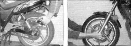
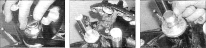
1The suspension components must be Front suspension 2While standing alongside the motorcycle, apply the front brake and push on the handlebars to compress the forks several times. See if they move up-and-down smoothly without binding. If binding is felt, the forks should be disassembled and inspected (see Chapter 6). 3 Inspect the area around the dust seals for signs of oil leakage, then carefully lever up the dust seals using a flat-bladed screwdriver and inspect the area around the fork seal (see illustration).If leakage is evident, the seals must be renewed (see Chapter 6). 4 Check the tightness of all suspension nuts and bolts to be sure none have worked loose. Rear suspension
5 Inspect the rear shock absorber mounting bolts for tightness. Inspect the shocks for pitting on the damper rods and fluid leakage. If leakage is found, the shocks should be renewed as a pair (see Chapter 6). 6 With the aid of an assistant to support the motorcycle, compress the rear suspension several times. It should move up and down freely without binding. If any binding is felt, the worn or faulty component must be identified and renewed. The problem could be due to either the shock absorber or the swingarm components. The shock absorbers can be removed individually for checking (see Chapter 6).
7 Support the motorcycle on its centre stand so that the rear wheel is off the ground. Grab the swingarm and attempt to rock it from side to side - there should be no discernible movement at the rear (see illustration).If there is any movement or a slight clicking can be heard, remove the caps and inspect the tightness of the swingarm nut (see illustration),referring to the torque settings specified at the beginning of Chapter 6, and re-check for movement. 8 Next, grasp the top of the rear wheel and pull it upwards - there should be no discernible freeplay before the shock absorbers begin to compress (see illustration).Any freeplay felt indicates worn shock absorber mountings. The worn components must be renewed (see Chapter 6). 9 To make an accurate assessment of the swingarm bearings, remove the rear wheel (see Chapter 7) and both rear shock absorbers (see Chapter 6). Grasp the rear of the swingarm with one hand and place your other hand at the junction of the swingarm and the frame. Try to move the rear of the swingarm from side-to-side. Any wear (play) in the bearings should be felt as movement between the swingarm and the frame at the front. If there is any play the swingarm will be felt to move forward and backward at the front (not from side-to-side). Next, move the swingarm up and down through its full travel. It should move freely, without any binding or rough spots. If any play In the swingarm is noted or if the swingarm does not move freely, the bearings must be removed for inspection or renewal (see Chapter 6).
19 Steering head bearings- check and adjustment 1 This motorcycle is equipped with caged ball Check 2 Support the motorcycle on its centre stand. Raise the front wheel off the ground by placing a support under the engine or by having an assistant push down on the rear. 3 Point the front wheel straight-ahead, then slowly move the handlebars from side-to-side. Any dents or roughness In the bearing races will be felt, and if the bearings are too tight the bars will not move smoothly and freely. If the bearings are damaged or the action is rough, they should be renewed (see Chapter 6). If the bearings are too tight they should be adjusted as described below. 4 Next, grasp the fork sliders and try to move them forward and backward (see illustration).Any looseness in the steering head bearings will be felt as front-to-rear movement of the forks. If play is felt in the bearings, adjust the steering head as follows.
Every 8000 miles 1.17
Date: 2016-01-14; view: 790
|