CATEGORIES:
BiologyChemistryConstructionCultureEcologyEconomyElectronicsFinanceGeographyHistoryInformaticsLawMathematicsMechanicsMedicineOtherPedagogyPhilosophyPhysicsPolicyPsychologySociologySportTourism
The Q measurement system implementationA custom FlexRIO digitizer module has been developed for a continuous signal acquisition and generation of an excitation signal in real time. Vendor ID 0xAB66 was obtained from National Instruments for production of the FlexRIO modules at JINR. In the following, FlexRIO digitizer module will be denoted by “Digitizer” (Figure 4). This module is an 8 layer PCB board with two 14-bit, 65MSPS ADCs(AD9244) with 5th order programmable bandpass analog filter (LTC6002), one 14-bit, 165MSPS DAC(DAC904), one analog input for the beam revolution frequency, which is taken from RF system, one analog input for synchronization with the start of injection. All input and output channels are galvanically isolated using the RF transformers (ADT1-6T). FlexRIO “Digitizer” module has a direct access to the I/O ports of the FPGA. Windowing of the input signal and FFT are implemented in the FPGA module. The signal processing starts simultaneously with the start of the input data accumulation and ends at the same time with the end of the data accumulation. It is all done inside FPGA, while the resources of the PXI system controller are not used and are available for other tasks (Figure 5). The “Digitizer” ADCs are used to digitize the amplified signals, which are coming from pick-up electrodes, mounted in X and Z planes. Two channel single-ended amplifiers have been developed for pick-up signal amplification. DAC is used to output the excitation signal. Further, the excitation signal is amplified by the AR 800A3A RF amplifier and then applied to kicker electrodes via impedance transformers (Figure 6).
Figure 4. FlexRIO “Digitizer” module.
The FlexRIO digitizer module inserted into 132-pin connector of the NI PXIe-7962R FPGA module for the PXI system (Figure 5). The FPGA module is DSP-focused and contains Virtex-5 SX50T FPGA which is programmable with the LabVIEW FPGA [5]. The FPGA module also contains 512 MB on-board DDR2 DRAM and slot with 132 single-ended I/O lines, which can be configured as 66 differential pairs. All I/O lines are customizable for the NI FlexRIO Adapter Module Development Kit. The FPGA Module is inserted into the PXI system crate NI PXIe-1082 which is 8-slot 3U PXI Express Chassis with a 1 GB/s per-slot back-plane data bus (Figure 5).
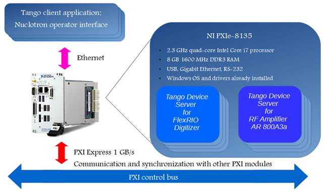
The PXI system crate also contains necessary additional modules such as Tegam-4040A – two channel differential amplifiers [6] and NI PXIe-8135, which is a high-performance Intel Core i7-3610QE processor-based embedded controller with OS Windows (Figure 7). The Tango device server (TDS) drivers have been implemented for every PXI module using C++, LabView and Python [7]. These drivers run on the PXI system controller. TDS is based on the TANGO Controls Server API and provides a remote control interface via ethernet (Figure 7).
The signals from the two ADC channels and the FFT results are stored in the internal memory DDR2 of the FPGA module. Built-in memory allows one to record the digitized data with the sampling frequency of 10 MHz from two 14-bit ADC channels for up to 4 seconds and the results of the FFT. After the end of the data accumulation results are transferred to the system controller PXIe-8135 via the DMA channel. The data transfer takes 0.9 sec. The TANGO Controls client application [7] is developed for remote control of the measurement system and displaying measured results. To excite transverse beam oscillations two methods were used – scanning frequency (chirp) and band-limited white noise. A scan signal is generated by a direct digital synthesis (DDS) in a predetermined frequency range and scanning time. DDS is implemented in the FPGA module and a generated signal is output from the FlexRIO “Digitizer” DAC. The DAC sampling frequency is filtered from the output signal by a 4th order elliptic low pass filter. The noise excitation signal has been implemented by generating a white noise with the subsequent digital filtering by a 9th order bandpass filter with an infinite impulse response in the desired frequency range. The generated signal is stored in the internal memory DDR2 of the FPGA module and outputs via “Digitizer” DAC. The maximum output excitation signal amplitude is 400mV, but it is amplified by the RF amplifier AR 800A3B with a variable gain from 1 to 10000. The high voltage signal is applied via step-up impedance transformers to the kicker. The signal amplitude applied to the kicker can be adjusted from 50 to 1000 Vpp. To provide switching of the high voltage excitation signal between the kicker X and the kicker Z a high voltage multiplexor has been developed on the basis of the high-voltage high-power (5kV, 1A) vacuum relay Gigavac (Figure 8). The HV multiplexor is controlled via the ethernet interface implemented with a help of Python binding for the Tango control system [7].
Figure 8. HV multiplexor with Gigavac vacuum relays and the ethernet interface Lantronix XPort.
Conclusions The betatron tune measurement system has been successfully tested during 51th run of the Nuclotron. The implementation of a high resolution FFT algorithm in an FPGA has allowed the acquisition of continuous real-time betatron tune. The implementation of a digital frequency synthesizer (DFS) inside the FPGA module allowed one to produce chirp and white noise excitation signals. The further improvements are planned to increase the resolution and sensitivity of the measurement system: · The development of the additional digitizer module with two AD7960, 18-Bit, 5 MSPS PulSAR differential ADC and ACAM TDC-GP22 time measurement controller for precision beam revolution frequency measurement with 90ps resolution. It will allow one to use diode detection technique which can improve the tune measurement resolution by one order of the magnitude [8]. The new digitizer module especially designed to be sampled at the revolution frequency. Simultaneous measurement using two FlexRIO digitizer modules can be a test for the measurement system – Q values should be the same. · The development of the differential amplifier for pickup based on AD8338, which is a variable gain amplifier (VGA) for applications that require a fully differential signal path, low power, low noise, and a well-defined gain over frequency. It has the voltage controlled gain range of 0dB to 80dB. This amplifier can significantly improve SNR and provide continuous signal fitting into the dynamic range of the ADC, which will allow one to track the betatron tune during injection and acceleration.
References [1] F. Zimmermann, Measurement and Correction of Accelerator Optics. Stanford Linear Accelerator Center (SLAC), Stanford University, Stanford, CA 94309, USA, SLAC-PUB-7844, June 1998. [2] G.Trubnikov, I.Meshkov, A.Butenko et al. NICA collider complex: challenges and perspectives. Status of the Project. JINR-SAR Round Table, 05 July 2015. [3] A. Boccardi, M. Gasior, R. Jones et al. The FPGA-based continious FFT tune measurement system for the LHC and its test at the CERN SPS. European Organization for Nuclear Research, CERN – AB Department, CERN-AB-2007-062, Geneva, Switzerland, August 2007. [4] M. Gasior, J.L. Gonzalez, Improving FFT frequency measurement resolution by parabolic and gaussian interpolation. European Organization for Nuclear Research, CERN – AB division, AB-Note-2004-021 BDI, Geneva, Switzerland, February 2004. [5] http://www.ni.com/labview/fpga [6] http://www.tegam.com/product.asp?modelNumber=4040A&redirected=1 [7] http://www.tango-controls.org [8] M. Gasior and R. Jones. High Sensitivity Tune Measurement by Direct Diode Detection. DIPAC05, Lyon, France, 2005.
Date: 2016-01-03; view: 1510
|