CATEGORIES:
BiologyChemistryConstructionCultureEcologyEconomyElectronicsFinanceGeographyHistoryInformaticsLawMathematicsMechanicsMedicineOtherPedagogyPhilosophyPhysicsPolicyPsychologySociologySportTourism
PARTS IN ENGINE ROOMCONDENSER The condenser in the air conditioning system is a device used to change high-pressure refrigerant vapor to a liquid. It does this by providing a means for emitting heat from the hot refrigerant to the cooler atmosphere. Parallel Flow type condenser improved the refrigerating efficiency and minimized than the Corrugated Type.
COMPRESSOR (SWASH PLATE TYPE)
SAFETY VALVE (Pressure Relief Valve) : Release the high-pressurized refrigerant and oil
RECEIVER AND DRIER
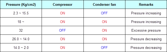
TRIPLE SWITCH There are 3 values of the set pressure, and it carries out the functions of dual switch, middle-pressure switch. It senses the pressure of the refrigerant and if the pressure is raised, close the switch and turns the cooling fan to the high-speed.
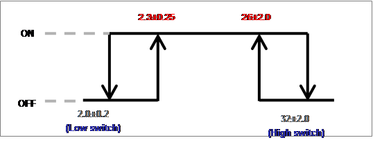
2. Switch on & off range •Low & high switch(kg/cm2)
• Middle switch(kg/cm2)
   
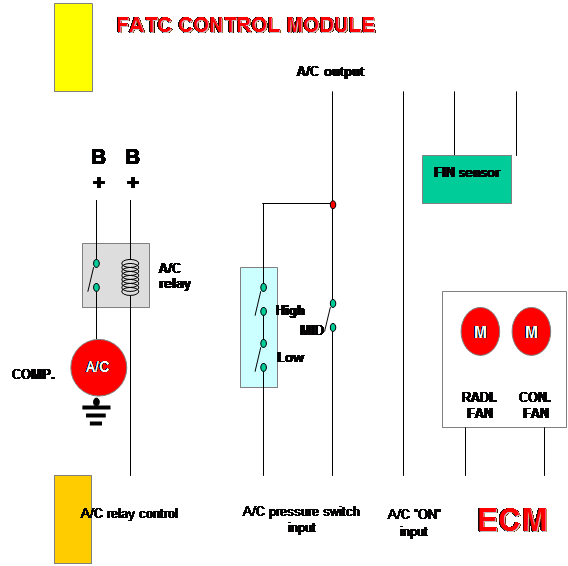
When the ignition switch is in the ON position, battery voltage is applied to the coil on the control side of the A/C relay. Whth the A/C switch ON, voltage passes through the normally closed contacts of the triple switch, and enters the ECM. Operating parameters permitting, when the ECM receives the A/C ON signal, it will apply a ground to the control side of the A/C relay, allowing the relay contacts to close. The allows battery voltage, which is always present at the load side of the A/C relay, to pass through its contacts to the coil in the A/C compressor magnetic clutch. When this happen, the A/C compressor begins to operate.
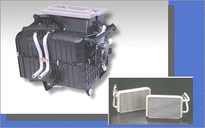
PARTS IN CABIN HEATER UNIT When engine coolant is allowed to flow through the heater core, heat from the coolant is transferred to the cooler air flowing through the fins of the heater core and into the passenger compartment.
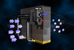
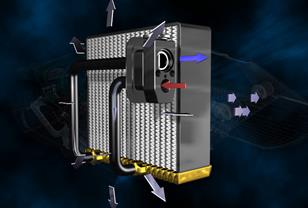
EVAPORATOR UNIT Function The evaporator is another heat exchanger in the air conditioning system. It has coils and fins like the condenser, but functions in reverse. The evaporator receives the cold, low-pressure atomize liquid refrigerant from the expansion valve. As this cold refrigerant passes through the coils of the evaporator, which vaporizes and absorbs heat from the passenger compartment.
Operation The state of the refrigerant immediately after the receiver drier is 100% liquid. As soon as the liquid pressure drop, it starts boil, and by doing so, absorbs heat. This heat is removed from the air passing over the cooling fins of the evaporator and causes the air to cool. Refrigerant properly entered into the evaporator should allow for 100% liquid just after passing over the receiver drier and 100% gas at the outlet.
EXPANSION VALVE The purpose of the expansion valve is to allow high-pressure liquid to expand as it enters the evaporator. It also controls, or meters the system to prevent the evaporator from flooding and freezing up. Expansion valve is inner equaling pressure type (Block type). Diaphragm is installed at the upper part of expansion valve. And, diaphragm upper chamber is connected to the sensing bulb.
AIR FILTER
Description
Life time Filter replacement period is 5,000~12,000km. But this can be shortening if the road condition is bad causing more dust and black smoke in the air.
* Remove the glove box.
Caution!! Make sure that mark on the filter.
Date: 2016-01-03; view: 759
|

 The compressor is the power unit of the A/C system. It pumps out refrigerant vapor under high-pressure and high heat on the discharge side (high side of system) and sucks in low-pressure vapor on the intake side (low side).

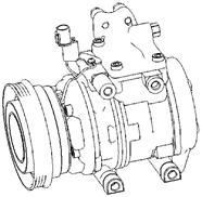

 - Operating pressure: 35.3~42.2kg/㎠


 (Normal operation) (Evaporator frizzing)


 Employing combination filter, dust and odor in the air is effectively removed
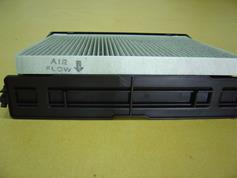
 3. How to replace
 * Pull the locking part of the air filter cover