CATEGORIES:
BiologyChemistryConstructionCultureEcologyEconomyElectronicsFinanceGeographyHistoryInformaticsLawMathematicsMechanicsMedicineOtherPedagogyPhilosophyPhysicsPolicyPsychologySociologySportTourism
Test and IndicationThere are two light emitting diodes (LEDs) and a test switch on the front of the VOR/MB receiver. The LEDs show receiver test status when you do a test of the VOR/MB receiver. The red control fail LED shows the status of the tune inputs. The green or red LRU status LED shows the status of the receiver test. You can do a test of the VOR/MB receiver from the NAV control panel or from the test switch on the VOR/MB receiver front panel. When you do a test of the VOR function of the left VOR/ MB receiver, you do a test of the VOR function and the marker beacon function at the same time.
VOR SYSTEM - VOR/MB RECEIVER General The VOR/LOC antenna is on the top of the vertical stabilizer. The VOR antenna receives RF signals in the frequency range of 108 MHz to 117.95 MHz. The antenna receives VOR and localizer frequencies. The VOR/LOC antenna sends VOR signals to both VOR/MB receivers.
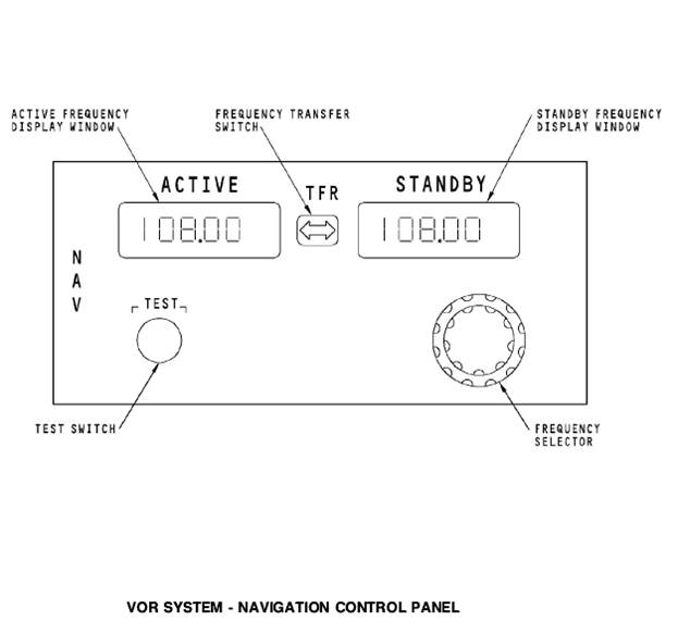
NAVIGATION CONTROL PANEL General The navigation (NAV) control panel supplies frequency inputs and test commands to the DME, ILS, and VOR navigation radios. Operation The NAV control panel has an active frequency display window and a standby frequency display window. The frequency that shows in the active frequency display window is the frequency that the navigation radios use for operation. The standby frequency display window shows the next frequency you want to use. The transfer switch is a momentary action switch that transfers the frequency in the standby frequency display window to the active frequency display window. When you push the switch, the frequency that is in the active frequency display window transfers to the standby frequency display window. The frequency select control is a continuous rotary knob. There is an inner knob and an outer knob. The outer knob sets the tens and ones digits. The inner knob sets the tenths and one hundreths digits. At power up, the frequency displays show the last frequency entry before power down. The NAV control panel continuous bite monitors control panel operation. The NAV control panel shows FAIL in the active and standby frequency display windows when there is a failure. An internal monitor in the NAV control panel monitors the 28v dc input. If the monitor does not see the 28v dc input, it will show the message BLANK in both the active and standby frequency display windows. When you set a VOR frequency in the range of 108 Mhz to 117.95 Mhz, the NAV control panel sends the frequency to the VOR/MB receivers and DME interrogators. The control panel sets the data word to the ILS receivers to NCD. Test When you push the NAV control panel test switch, a test command goes out to the VOR/MB receiver, ILS receiver, and DME interrogator. If a VOR frequency shows in the active frequency window, the test command goes to only the VOR/MB receiver. IF an ILS frequency shows in the active frequency window, the control panel sends a test command to only the ILS receiver. If there is a DME frequency that is paired with the VOR or ILS frequency, a test command also goes to the DME interrogators. When you do a test of the master dim and test system, the NAV control panel shows 188.88. The display shows for two seconds on then one second off until the test is complete.
Date: 2015-12-24; view: 1187
|