CATEGORIES:
BiologyChemistryConstructionCultureEcologyEconomyElectronicsFinanceGeographyHistoryInformaticsLawMathematicsMechanicsMedicineOtherPedagogyPhilosophyPhysicsPolicyPsychologySociologySportTourism
Task 1. Computation of stepped rod in tension-compressionPREFACE The method guide is intended for the second – year students of specialities 6.092100 “Industrial and civil engineering”, 6.100100 “Manufacture, maintenance and repair of aircraft and engines” and 6.090500 “Gas turbine plants and compressor stations”. It includes the tasks and recommendations for performing computation – design work for speciality 6.092100 (tasks 1-2 for module 1 and 3-5 for module 2) and home tasks for specialities 6.100100 and 6.090500 for the following parts of the course “Strength of materials”: tension-compression, stress state at point, geometrical characteristics of sections, bending and torsion. The method guide is constructed according to “Strength of materials” course syllabus. The main purpose of studying this course is to gain knowledge in strength, rigidity and stability analysis of structures, constructions, machines and their elements. While studying the "Strength of materials" course the students will gain skills for designing new structures and conducting check computations of existing structures during their operation and repair. In the "Strength of materials" course the theoretical questions will be closely tied to the engineering computations and to practice solutions of concrete problems of the structural members. One of the intensive methods of credit module system of education for development of computation skills and engineering thinking is the student's independent work including computation-graphic work and home tasks performance.
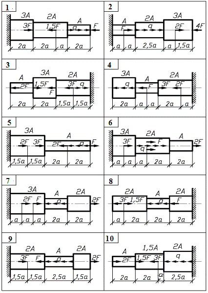
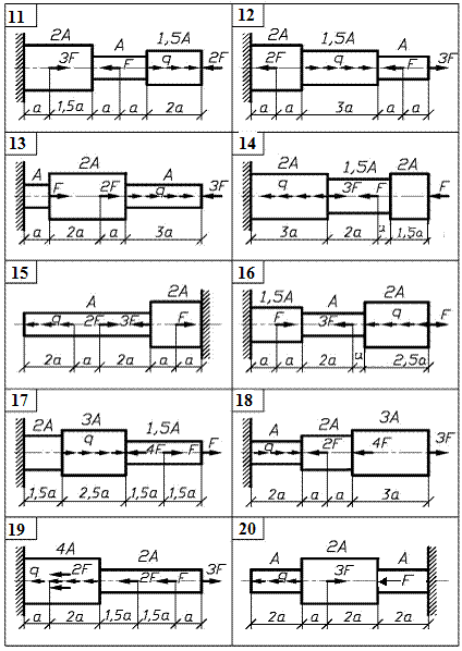
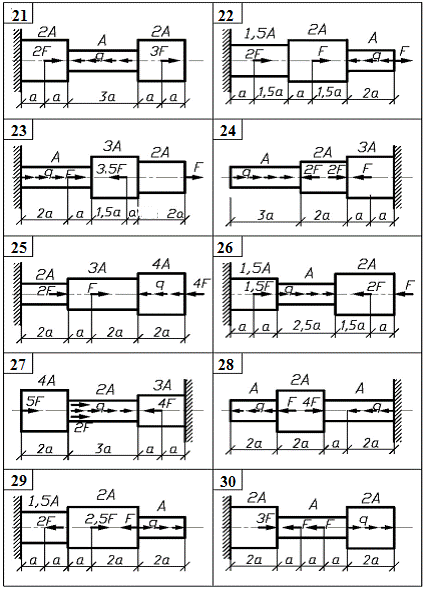
Module 1 Stress state and deformational analysis Of structural parts at THE strength and rigidity calculations Task 1. Computation of stepped rod in tension-compression The stepped rod (fig. 1) is under the action of longitudinal axial forces F and distributed load q. To carry out the analysis of the rod. Take the data for computation from table 1 and material mark from table 2. accept the safety factor as following: - for ductile materials ny = 1,4 … 1,6; - for brittle materials ns = 2,5 … 3,0.
Fig.1. (see also p.5)
Fig.1. Continued (see also p.6)
Fig.1. Ending Order of work 1. Using the method of the section determine the normal axial force Nand normal stress s at each section of the rod and draw diagram N and s to scale. 2. Determine the absolute elongation Dl of each section and draw the diagram of the cross-section motion along the rod. 3. Calculate allowable values of stress, determine the dangerous section of the rod and make the conclusion about strength of the rod.
Table 1
Table 2
Date: 2015-12-24; view: 922
|