CATEGORIES:
BiologyChemistryConstructionCultureEcologyEconomyElectronicsFinanceGeographyHistoryInformaticsLawMathematicsMechanicsMedicineOtherPedagogyPhilosophyPhysicsPolicyPsychologySociologySportTourism
Working with Idealized JointsIdealized joints connect two parts. The parts can be rigid bodies, flexible bodies, or point masses. You can place idealized joints anywhere in your model. ADAMS/View supports two types of idealized joints: simple and complex. Simple joints directly connect bodies and include the following: Table1 2.3 Simple joints in ADAMS/View
Complex joints indirectly connect parts by coupling simple joints. They include: Gear Joint and Coupler Joint. See table 2.4.
Table1 2.4 Complex joints in ADAMS/View
To create a simple idealized joint: 1) From the Jointtool stack or palette, select the joint tool representing the idealized joint that you want to create. 2) In the settings container, specify the following: How you want the joint connected to parts. You can select the following: Ÿ 1 location (Bodies Implicit) -Lets you select the location of the joint and have ADAMS/View determine the two parts that should be connected. ADAMS/View selects the parts closest to the joint location. If there is only one part near the joint, ADAMS/View connects the joint to that part and ground. Ÿ 2 Bodies - 1 Location -Lets you explicitly select the two parts to be connected by the joint and the location of the joint. The joint remains fixed on the first part and moves relative to the second part. Ÿ 2 Bodies - 2 Locations - Lets you explicitly select the two parts to be connected by the joint and the location of the joint on each part. You should use this option if you are working in exploded view. How you want the joint oriented. You can select: Ÿ Normal to Grid -Lets you orient the joint along the current working grid, if it is displayed, or normal to the screen. Ÿ Pick Geometry Feature -Lets you orient the joint along a direction vector on a feature in your model, such as the face of a part. 3) Select the first part to be connected using the left mouse button. If you selected to explicitly select the parts to be connected, select the second part in your model using the left mouse button. 4) Place the cursor where you want the joint to be located, and click the left mouse button. If you selected to specify its location on each part, place the cursor on the second location, and click the left mouse button. 5) If you selected to orient the joint along a direction vector on a feature, move the cursor around in your model to display an arrow representing the direction along a feature where you want the joint oriented. When the direction vector represents the correct orientation, click the left mouse button. To create a gear joint: 1)To create a gear, select the Geartool 2)In the Gear Nametext box, enter or change the name for the gear. If you are creating a gear, ADAMS/View assigns a default name to the gear. 3) In the Adams Idtext box, assign a unique ID number to the gear. The ID is an integer number used to identify the gear in the ADAMS/Solver dataset. You only need to specify an ADAMS ID if you are exporting the model to an ADAMS/Solver dataset, and you want to control the numbering scheme used in the file. Enter a positive integer for the ID or enter 0 to let ADAMS set the ID for you. 4) In the Commentstext box, add or change any comments about the gear to help you manage and identify the gear. You can enter any alphanumeric characters. The comments appear in the information window when you select to display information about the gear, in the ADAMS/View log file, and in a command or dataset file when you export your model to these types of files. 5) In the Joint Nametext box, enter or change the two translational, revolute, or cylindrical joints to be geared together. ADAMS/View automatically separates the joint names with a comma (,). 6) In the Common Velocity Markertext box, enter or change the marker defining the point of contact between the geared parts. You need to make sure the z-axis of the common velocity marker points in the direction of motion of the gear teeth that are in contact. To create a marker, right-click the Common Velocity Markertext box, and then select Create. 7) Select OK. To create a coupler joint: 1) From the Jointtool stack or palette, select the Couplertool 2) Select the driver joint to which the second joint is coupled. 3) Select the coupled joint that follows the driver joint. Date: 2015-12-18; view: 1419
|


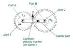


 on the Jointtool stack or palette. The Constraint Create Complex Joint Gear dialog box appears.
 .
.