CATEGORIES:
BiologyChemistryConstructionCultureEcologyEconomyElectronicsFinanceGeographyHistoryInformaticsLawMathematicsMechanicsMedicineOtherPedagogyPhilosophyPhysicsPolicyPsychologySociologySportTourism
Specifying Working DirectoryBy default, ADAMS/View searches for and saves all files in the directory from which you ran ADAMS/View. You can change the working directory. To change the working directory for the current session: 1) On the Filemenu, select Select Directory. 2) Select the directory in which ADAMS/View should save files. 3) Select OK.
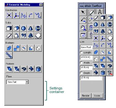
2 Building Models in ADAMS/View ADAMS/View provides a complete library of parts that you can create. ADAMS/View provides you with three different types of parts. Ÿ Rigid Bodies:Parts in your models that have mass and inertia properties. They cannot deform. Ÿ Flexible Bodies: Parts that have mass and inertia properties and can bend when forces are applied to them. Basic ADAMS/View provides you with the ability to create discrete flexible links. For more functionality, you can purchase ADAMS/Flex. Ÿ Point Masses: Parts that have only mass. They have no extent and, therefore, no inertia properties. In addition, ADAMS/View provides a ground part that is already created for you. The ground part is the only part in your model that must remain stationary at all times. ADAMS/View creates the ground part automatically when you create a model. You can also define a new or existing part as ground. The ground part does not have mass properties or initial velocities and does not add degrees of freedom into your model. Creating Parts You can create rigid body geometry using the tools on the Geometric Modeling palette or the Geometric Modelingtool stack on the Main toolbox. The palette and tool stack contain the same tools so you can choose whichever one you are most comfortable using. The Geometric Modeling palette and tool stack are shown in figure 2.1. As you create geometry, ADAMS/View provides settings to assist you in defining the geometry. It provides the settings in a container at the bottom of the palette or Main toolbox. The settings change depending on the type of geometry that you are creating. For example, Figure 2.1 shows the length, width, and depth values associated with creating link geometry. You can use the settings to control how you want ADAMS/View to define the geometry. For example, when you create a link, ADAMS/View lets you specify its width, length, and height before creating it. Then, as you create the link, these dimensions are set regardless of how you move the mouse. You can also define design variables or expressions for these setting values. To display the Geometric Modeling palette: From the Buildmenu, select Bodies/Geometry. To display the contents of the Geometric Modeling tool stack: From the Main toolbox, right-click the Geometric Modelingtool stacks. By default, the Linktool
Geometric Modeling palette Geometric Modeling tool stack on Main toolbox Date: 2015-12-18; view: 741
|
 appears at the top of the tool stack.