CATEGORIES:
BiologyChemistryConstructionCultureEcologyEconomyElectronicsFinanceGeographyHistoryInformaticsLawMathematicsMechanicsMedicineOtherPedagogyPhilosophyPhysicsPolicyPsychologySociologySportTourism
More about communication bus

Figure 2.9Interconnection of CPU with Memory and I/O
Instructions to be executed by a CPU are retrieved from main memory, interpreted by it and executed. CPU is connected to main memory by a set of parallel wires called Address Bus, which carries address bits to the MAR (Memory Address Register) and the Data Bus, which carries data/instructions from CPU to MDR (Memory Data Register) of main memory. The control bus carries instructions to carry out operations such as Read/Write from or to memory and also input/output operations. Number of parallel wires is called bus width. If MAR has 24 bits( to address upto 16 MB memory) then the address bus width is 24. The size of data bus from memory to CPU equals number of bits in an instruction also called CPU word length. Most of the processors used in PCs have a word length of 32 bits and thus the data bus width is 32 bits. The instruction width of I A - 64 by Intel is 128 and thus the data bus width is 128 bits. The number of bits in the control bus is normally around 16. This connection of buses, namely Address bus, Data bus and Control bus is called - System Bus. The bus standards allow diverse manufacturers of various peripheral devices to design devices to easily connect to PCs.
The CPU, memory and integrated circuits to connect I/O units to the CPU and main memory are all mounted on what is called a motherboard. The motherboard also has a ROM where a program called BIOS (Basic Input Output System) is stored to control all the peripheral devices connected to a computer.
A motherboard has a set of connection points called ports to connect units such as disk, VDU, keyboard etc. In a parallel port data bits are transmitted in parallel (16 or 32 bitssimultaneously) to peripherals via a set of parallel wires (called ribbon cables). Serial ports transmit single bits serially, one after another. Faster peripherals such as hard disk are connected to parallel ports. Slower devices such as keyboard are connected to serial port. A standard serial port is known as Universal Serial Bus (USB).
Communication Ports
A communication port is mounted in a slot on the computer for easy plugging/unplugging of a peripheral device.
Serial Port
Through this port the information travels in and out one bit at a time. Serial ports come in the form of 9-pin or 25-pin male connector. These ports are often known as communication (COM) port. Mouse, modem etc. are connected using serial port though now mostly they are been replaced by USB port.
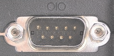
Figure 2.10 Serial Port Socket
Parallel Port
Through this port the several data signals are sent simultaneously over several parallel channels. Parallel ports come in the form of 25-pin female connector. These ports are used to connect printer, scanner etc.
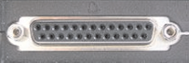
Figure 2.11 Parallel Port Socket
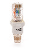
RJ 45 Port
This port is used for thernet connections and can be used between computer and any networked device, such as a cable modem or a network hub. It is a 8 wire connector.
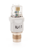
RJ 11 Port
This port is for connecting to a telephone line. It has six-wire conductors in it and is smaller than RJ45.
USB Port :
USB stands for Universal Serial Bus, used for short distance digital data communications. This port allows data transfer between devices with little electric power.
| 
| 
| 
|
| Figure 2.12 RJ11 and RJ 45 Port Socket |
Date: 2015-12-17; view: 973
| <== previous page | | | next page ==> |
| Arithmetic and Logical Unit | | | COMPUTER OPERATING SYSTEM SOFTWARE |