CATEGORIES:
BiologyChemistryConstructionCultureEcologyEconomyElectronicsFinanceGeographyHistoryInformaticsLawMathematicsMechanicsMedicineOtherPedagogyPhilosophyPhysicsPolicyPsychologySociologySportTourism
Co-channel interference
Generally, a mobile will receive a wanted carrier signal (C) from the base station serving the cell in which it is located, and in addition, interfering signals (1) from other cells. The carrier to interference ratio C/I is related to the re-use ratio D/R. Cellular radio systems are designed to tolerate a certain amount of interference, but beyond this, speech quality will be severely degraded. The TACS cellular system, forexample, will work with a C/I down to around 17dB. This lower limit on C/I effectively sets the minimum D/R ratio that can be used.
The two key factors in ensuring that good quality transmission can occur between a mobile and base station are that the wanted signal strength is sufficiently large, that is, above the receiver threshold sensitivity, and that the interference level is low enough to give an adequate C/I ratio. Both ofthese factors depend on the radio propagation between the mobile and base stations.
Radio propagation
There are a number of elements which contribute to the received signal strength at a mobile. Firstly, fora line of sight path, there is a free space path loss which is related to the radial distance between base station and mobile.
In addition to this loss, where there is no direct line of sight path, there will be a diffraction loss resulting from obstructions in the path. In general there will also be an effect due to multiple signals arriving at the mobile due to reflections from buildings and other terrain features. This multi-path effect will result in signals either adding constructively or destructively.
As a mobile moves around within a cell it will experience varying signal, as shown in Figure 47.6, due to these factors. Fast fading is caused by the multipath effect, and occurs with only a small movement of the mobile. This is also known as Rayleigh fading. Slow fading is mainly caused by terrain features and occurs over large distances ofhundreds of metres.
In addition, the path loss is also dependent upon the type of terrain, for example, urban with dense buildings, or rural with trees, or even over water. The height of the mobile and base station above ground level also affects the propagation, although the mobile height is not usually a variable.
Predicting path loss is an essential part of radio planning, and because of the large number of contributing factors, empirically based formulae are used. The most widely used formula is the Hata model (Hata, 1980) which is based on the propagation measurement results of Okumura et al. (1968).
Hata's basic formula forthe total path loss, Lp, is given by Equation 47.2 where f is the carrier frequency in MHz, k is the base station antenna height, h is the mobile antenna height, R is the radial distance in kilometres, and a(h ) is the mobile antenna height correction factor.
Lp (dB) = 69.55 + 26.16log(fc) – 13.82log(hb) – a(hm) + (44.9 – 6.55log(hb))logR (47.2)
Correction factors can be used to take into account the type of terrain
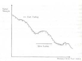
Figure 47.6Fading effects
Date: 2015-12-11; view: 1053
| <== previous page | | | next page ==> |
| Location registration | | | Practical radio planning |