CATEGORIES:
BiologyChemistryConstructionCultureEcologyEconomyElectronicsFinanceGeographyHistoryInformaticsLawMathematicsMechanicsMedicineOtherPedagogyPhilosophyPhysicsPolicyPsychologySociologySportTourism
Heat exchangers in traditional indirect adiabatic cooling
Indirect evaporative cooling efficiency depends not only on the state of the air, but also on the efficiency of the heat exchanger. The main types of the heat exchangers are plate heat exchangers, rotating heat exchangers and air-fluid-air heat exchangers.
System with the use of plate heat exchangers is simple in design, reliable in operation and has minimal maintenance costs. The heat exchanger is made of metal plates, which create a system of canals, where are two flows of air. The main advantage of the plate heat exchangers is that air flows do not mix, so the system can be used in "clean" areas (medicine, pharmaceutics microelectronics, etc.). While the main drawback of the system is the probability of freezing of the exchangers exhaust line.
The main types of plate heat exchangers are shown in the Figure 4 /5/.
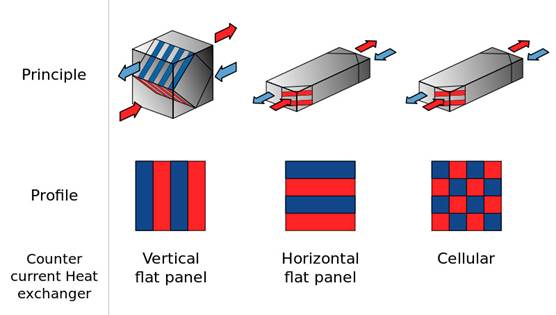
FIGURE 4. Different types of plate heat exchangers /5/
According to the Figure 4, from left to right are shown: cross flow heat exchanger, counter flow heat exchanger and cellular counter flow heat exchanger. The most common at this time is a cross flow heat exchanger, but it has smallest efficiency among other types (50 – 70 %). The efficiency of the counter flow heat exchanger is about 70 – 80 %. And the efficiency of the counter flow cellular heat exchanger can reach 95 %. /6./
Rotating heat exchanger is a device in which heat transfer is the result of accumulation of heat in rotating wheel (corrugated steel sheet, folded so as to get channels for horizontal air flow). The advantage of rotary heat exchangers is very high efficiency of heat recovery. The disadvantage is the mixture of air streams so these exchangers are not applicable in places where is needed full separation of supply and exhaust air. The schematic diagram of the rotating heat exchanger is shown in the Figure 5 /5/.
FIGURE 5. The schematic diagram of the rotating heat exchanger /5/
The air-fluid-air heat exchangers are used in cases, when the distance between the supply and exhaust units is large enough and mixing of air streams is unacceptable. This system consists of two heat exchangers which are located in the supply and exhaust ducts and connected with the piping system filled with heat transfer agent. One of the main advantages of the system is that the heat transfer agent is nonfreezing fluid, which ensures stable operation without freezing coils. But because there are two intermediate heat exchangers, heat transfer efficiency is reduced by 40 - 50 %. /6./
Date: 2015-12-11; view: 1420
| <== previous page | | | next page ==> |
| The process of adiabatic cooling | | | Maisotsenko combustion turbine cycle |