CATEGORIES:
BiologyChemistryConstructionCultureEcologyEconomyElectronicsFinanceGeographyHistoryInformaticsLawMathematicsMechanicsMedicineOtherPedagogyPhilosophyPhysicsPolicyPsychologySociologySportTourism
High anisotropy alloys.MAGNET It is any material capable of attracting iron and producing a magnetic field outside itself. By the end of the 19th century all the known elements and many compounds had been tested for magnetism, and all were found to have some magnetic property. The most common was the property of diamagnetism, the name given to materials exhibiting a weak repulsion by both poles of a magnet. Some materials, such as chromium, showed paramagnetism, being capable of weak induced magnetization when brought near a magnet. This magnetization disappears when the magnet is removed. Only three elements, iron, nickel, and cobalt, showed the property of ferromagnetism (i.e., the capability of remaining permanently magnetized).
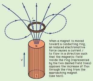
Magnetization process. The quantities now used in characterizing magnetization were defined and named by William Thomson (Lord Kelvin) in 1850. The symbol B denotes the magnitude of magnetic flux density inside a magnetized body, and the symbol H denotes the magnitude of magnetizing force, or magnetic field, producing it. The two are represented by the equation B = mH, in which the Greek letter mu, m, symbolizes the permeability of the material and is a measure of the intensity of magnetization that can be produced in it by a given magnetic field. The modern units of the International Standard (SI) system for B are teslas (T) or webers per square metre (Wb/m2) and for H are amperes per metre (A/m). The units were formerly called, respectively, gauss and oersted. The units of m are henrys per metre.All ferromagnetic materials exhibit the phenomenon of hysteresis, a lag in response to changing forces based on energy losses resulting from internal friction. If B is measured for various values of H and the results are plotted in graphic form, the result is a loop of the type shown in the accompanying figure, called a hysteresis loop. The name describes the situation in which the path followed by the values of B while H is increasing differs from that followed as H is decreasing. With the aid of this diagram, the characteristics needed to describe the performance of a material to be used as a magnet can be defined. Bs is the saturation flux density and is a measure of how strongly the material can be magnetized. Br is the remanent flux density and is the residual, permanent magnetization left after the magnetizing field is removed; this latter is obviously a measure of quality for a permanent magnet. It is usually measured in webers per square metre. In order to demagnetize the specimen from its remanent state, it is necessary to apply a reversed magnetizing field, opposing the magnetization in the specimen. The magnitude of field necessary to reduce the magnetization to zero is Hc, the coercive force, measured in amperes per metre. For a permanent magnet to retain its magnetization without loss over a long period of time, Hc should be as large as possible. The combination of large Br and large Hc will generally be found in a material with a large saturation flux density that requires a large field to magnetize it. Thus, permanent-magnet materials are often characterized by quoting the maximum value of the product of B and H, (BH)max, which the material can achieve. This product (BH)max is a measure of the minimum vol ume of permanent-magnet material required to produce a required flux density in a given gap and is sometimes referred to as the energy product.It was suggested in 1907 that a ferromagnetic material is composed of a large number of small volumes called domains, each of which is magnetized to saturation. In 1931 the existence of such domains was first demonstrated by direct experiment. The ferromagnetic body as a whole appears unmagnetized when the directions of the individual domain magnetizations are distributed at random. Each domain is separated from its neighbours by a domain wall. In the wall region, the direction of magnetization turns from that of one domain to that of its neighbour. The process of magnetization, starting from a perfect unmagnetized state, comprises three stages: (1) Low magnetizing field. Reversible movements of the domain walls occur such that domains oriented in the general direction of the magnetizing field grow at the expense of those unfavourably oriented; the walls return to their original position on removal of the magnetizing field, and there is no remanent magnetization. (2) Medium magnetizing field. Larger movements of domain walls occur, many of which are irreversible, and the volume of favourably oriented domains is much increased. On removal of the field, all the walls do not return to their original positions, and there is a remanent magnetization. (3) High magnetizing field. Large movements of domain walls occur such that many are swept out of the specimen completely. The directions of magnetization in the remaining domains gradually rotate, as the field is increased, until the magnetization is everywhere parallel to the field and the material is magnetized to saturation. On removal of the field, domain walls reappear and the domain magnetizations may rotate away from the original field direction. The remanent magnetization has its maximum value.The values of Br, Hc, and (BH)max will depend on the ease with which domain walls can move through the material and domain magnetization can rotate. Discontinuities or imperfections in the material provide obstacles to domain wall movement. Thus, once the magnetizing field has driven the wall past an obstacle, the wall will not be able to return to its original position unless a reversed field is applied to drive it back again. The effect of these obstacles is, therefore, to increase the remanence. Conversely, in a pure, homogeneous material, in which there are few imperfections, it will be easy to magnetize the material to saturation with relatively low fields, and the remanent magnetization will be small.Demagnetization and magnetic anisotropy. As far as domain rotation is concerned, there are two important factors to be considered, demagnetization and magnetic anisotropy (exhibition of different magnetic properties when measured along axes in different directions). The first of these concerns the shape of a magnetized specimen. Any magnet generates a magnetic field in the space surrounding it. The direction of the lines of force of this field, defined by the direction of the force exerted by the field on a (hypothetical) single magnetic north pole, is opposite to the direction of field used to magnetize it originally. Thus, every magnet exists in a self-generated field that has a direction such as to tend to demagnetize the specimen. This phenomenon is described by the demagnetizing factor. If the magnetic lines of force can be confined to the magnet and not allowed to escape into the surrounding medium, the demagnetizing effect will be absent. Thus a toroidal (ring-shaped) magnet, magnetized around its perimeter so that all the lines of force are closed loops within the material, will not try to demagnetize itself. For bar magnets, demagnetization can be minimized by keeping them in pairs, laid parallel with north and south poles adjacent and with a soft-iron keeper laid across each end.The relevance of demagnetization to domain rotation arises from the fact that the demagnetizing field may be looked upon as a store of magnetic energy. Like all natural systems, the magnet, in the absence of constraints, will try to maintain its magnetization in a direction such as to minimize stored energy; i.e., to make the demagnetizing field as small as possible. To rotate the magnetization away from this minimum-energy position requires work to be done to provide the increase in energy stored in the increased demagnetizing field. Thus, if an attempt is made to rotate the magnetization of a domain away from its natural minimum-energy position, the rotation can be said to be hindered in the sense that work must be done by an applied field to promote the rotation against the demagnetizing forces. This phenomenon is often called shape anisotropy because it arises from the domain's geometry which may, in turn, be determined by the overall shape of the specimen.Similar minimum-energy considerations are involved in the second mechanism hindering domain rotation, namely magnetocrystalline anisotropy. It was first observed in 1847 that in crystals of magnetic material there appeared to exist preferred directions for the magnetization. This phenomenon has to do with the symmetry of the atomic arrangements in the crystal. For example, in iron, which has a cubic crystalline form, it is easier to magnetize the crystal along the directions of the edges of the cube than in any other direction. Thus the six cube-edge directions are easy directions of magnetization, and the magnetization of the crystal is termed anisotropic.Magnetic anisotropy can also be induced by strain in a material. The magnetization tends to align itself in accordance with or perpendicular to the direction of the in-built strain. Some magnetic alloys also exhibit the phenomenon of induced magnetic anisotropy. If an external magnetic field is applied to the material while it is annealed at a high temperature, an easy direction for magnetization is found to be induced in a direction coinciding with that of the applied field.The above description explains why steel makes a better permanent magnet than does soft iron. The carbon in steel causes the precipitation of tiny crystallites of iron carbide in the iron that form what is called a second phase. The phase boundaries between the precipitate particles and the host iron form obstacles to domain wall movement, and thus the coercive force and remanence are raised compared with pure iron.The best permanent magnet, however, would be one in which the domain walls were all locked permanently in position and the magnetizations of all the domains were aligned parallel to each other. This situation can be visualized as the result of assembling the magnet from a large number of particles having a high value of saturation magnetization, each of which is a single domain, each having a uniaxial anisotropy in the desired direction, and each aligned with its magnetization parallel to all the others.Powder magnets. The problem of producing magnets composed of compacted powders is essentially that of controlling particle sizes so that they are small enough to comprise a single domain and yet not so small as to lose their ferromagnetic properties altogether. The advantage of such magnets is that they can readily be molded and machined into desired shapes. The disadvantage of powder magnets is that when single-domain particles are packed together they are subject to strong magnetic interactions that reduce the coercive force and, to a lesser extent, the remanent magnetization. The nature of the interaction is essentially a reduction of a given particle's demagnetizing field caused by the presence of its neighbours, and the interaction limits the maximum values of Hc and (BH)max that can be achieved. More success has attended the development of magnetic alloys. High anisotropy alloys. The materials described above depend on shape for their large uniaxial anisotropy. Much work has also been done on materials having a large uniaxial magnetocrystalline anisotropy. Of these, the most successful have been cobalt–platinum (CoPt) and manganese–bismuth (MnBi) alloys. Alnico alloys. High coercive force will be obtained where domain wall motion can be inhibited. This condition can occur in an alloy in which two phases coexist, especially if one phase is a finely divided precipitate in a matrix of the other. Alloys containing the three elements iron, nickel, and aluminum show just such behaviour; and permanent magnet materials based on this system, with various additives, such as cobalt, copper, or titanium, are generally referred to as Alnico alloys. Rare-earth –cobalt alloys. Isolated atoms of many elements have finite magnetic moments (i.e., the atoms are themselves tiny magnets). When the atoms are brought together in the solid form of the element, however, most interact in such a way that their magnetism cancels out and the solid is not ferromagnetic. Only in iron, nickel, and cobalt, of the common elements, does the cancelling-out process leave an effective net magnetic moment per atom in the vicinity of room temperature and above. Unfortunately, however, it loses its ferromagnetism at temperatures above 16° C (60° F) so that it is not of practical importance. Several of the rare-earth elements show ferromagnetic behaviour at extremely low temperatures, and many of them have large atomic moments. They are not, however, of great practical value. Barium ferrites. Barium ferrite, essentially BaO:6Fe2O3, is a variation of the basic magnetic iron-oxide magnetite but has a hexagonal crystalline form. This configuration gives it a very high uniaxial magnetic anisotropy capable of producing high values of Hc. The powdered material can be magnetically aligned and then compacted and sintered. The temperature and duration of the sintering process determines the size of the crystallites and provides a means of tailoring the properties of the magnet. For very small crystallites the coercive force is high and the remanence is in the region of half the saturation flux density. Larger crystallites give higher Br but lower Hc. This material has been widely used in the television industry for focussing magnets for television tubes.A further development of commercial importance is to bond the powdered ferrite by a synthetic resin or rubber to give either individual moldings or extruded strips, or sheets, that are semiflexible and can be cut with knives. This material has been used as a combination gasket (to make airtight) and magnetic closure for refrigerator doors. Lenz’s law In electromagnetism, statement that an induced electric current flows in a direction such that the current opposes the change that induced it. This law was deduced in 1834 by the Russian physicist Heinrich Friedrich Emil Lenz (1804–65). Thrusting a pole of a permanent bar magnet through a coil of wire, for example, induces an electric current in the coil; the current in turn sets up a magnetic field around the coil, making it a magnet. Lenz's law indicates the direction of the induced current. Because like magnetic poles repel each other, Lenz's law states that when the north pole of the bar magnet is approaching the coil, the induced current flows in such a way as to make the side of the coil nearest the pole of the bar magnet itself a north pole to oppose the approaching bar magnet. Upon withdrawing the bar magnet from the coil, the induced current reverses itself, and the near side of the coil becomes a south pole to produce an attracting force on the receding bar magnet.A small amount of work, therefore, is done in pushing the magnet into the coil and in pulling it out against the magnetic effect of the induced current. The small amount of energy represented by this work manifests itself as a slight heating effect, the result of the induced current encountering resistance in the material of the coil. Lenz's law upholds the general principle of the conservation of energy. If the current were induced in the opposite direction, its action would spontaneously draw the bar magnet into the coil in addition to the heating effect, which would violate conservation of energy.
Demonstration of Faraday's and Lenz's laws.
Date: 2015-12-11; view: 904
|