CATEGORIES:
BiologyChemistryConstructionCultureEcologyEconomyElectronicsFinanceGeographyHistoryInformaticsLawMathematicsMechanicsMedicineOtherPedagogyPhilosophyPhysicsPolicyPsychologySociologySportTourism
Introduction to Polymer Science and TechnologyPolymer processing
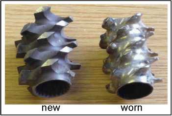
restrictive kneading conveyor shorterpitch Figure 3.26Examples of different screw elements Mixing elements contain cut-outs and are designed to convey material forward in the barrel, while dividing and recombining the melt stream to provide mainly distributive mixing. They can suffer excessive wear, see Figure 3.27, and with some material mixes, e.g., wood flour and a polymer, this may happen in a short period of time.
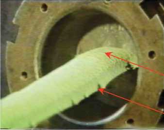
Figure 3.27Photograph of new and worn mixing elements Extrusion problemsinclude excessive die swell, melt fracture, shark skin, output fluctuations (causes dimensional variations), thermal degradation (discolouration), poor mixing (streaks on the extrudate surface), bubbles (entrapped gas) and impurities. Gels (small bits of higher-molecular-weight material or overheated/degraded bits of polymer in the die or contamination that reflect and transmit light differently from the rest of the polymer) and specks (under extrusion shear forces some of these particles become elongated, referred to as "fisheyes") are of particular concern in clear film. Detailed description of these problems and how to avoid them can be found in Strong (1996, p280) and Morton-Jones 1989. Die swell,a function of flow and shear rates, is described by Strong (1996, p275) as, "die swell is caused by the viscoelastic nature of the polymer melt. Stress relaxation (dissipation of stresses) tends to be slow in viscoelastic materials. The compressive forces that are needed to push the polymer melt through the small die orifices are not completely relieved by the time the polymer exits the die. The polymer therefore expands when it exits the die in response to the relaxation of the residual compressive stresses, thus returning to a shape the material had just before it entered the constrictive land portion of the die. This shape recovery appears as a swelling of the polymer after the die. Die swell can be reduced by extending the land length so that the polymer has sufficient time under the compressed conditions to dissipate the compression forces. Increasing temperature will also reduce die swell as it imparts the energy needed to disentangle the molecules." Introduction to Polymer Science and Technology Polymer processing Melt fracturecan occur anywhere in an extrudate due to tensile stresses on the melt exceeding the critical shear/tear stress. When it is confined to the surface it can generate a pattern known as sharkskin.The sharkskin is perpendicular distortion/roughness - a pattern consisting of lines of ripples running across the flow direction. The pattern is generated by the tearing of the melt on the extrudate surface: the melt passing through the die has a parabolic flow front, i.e., the flow is faster in the centre of the die than it is near the die surfaces. Upon exiting the die the outer layer has to accelerate to maintain the flat flow front that the extrudate now assumes. Accordingly the tension increases at the extrudate surface and if it exceeds its tensile strength, the melt will tear. Tearing relieves the tension but it immediately increases again and, unless corrected, this process gets repeated. Sharkskin can also be caused by the instability known as "stick-slip" in the die. The type of metal that the die is made from and the level of smoothness of the die surfaces can influence the occurrence of the stick-slip phenomenon, e.g., brass dies have been found to reduce sharkskin and stick-slip instabilities. Figure 3.28 shows an extrudate emerging from the die, exhibiting small magnitudes of die swell, sharkskin and melt fracture. An example of melt fracture is also shown in Figure 3.29 for a plastic-board extrudate. Introduction to Polymer Science and Technology Polymer processing
sharkskin .melt fracture
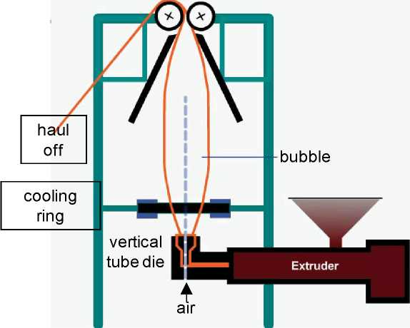
Figure 3.29Extrudates exhibiting (a) no melt fracture and (b) melt fracture along the edges Types of extrusion processesinclude: - blown (bubble process) film cable coating cast film extrusion + blow moulding extrusion + thermoforming fibre mesh/netting profile extrusion sheet extrusion strand pelletising tube or pipe. Some of these processes are described in more detail below. Introduction to Polymer Science and Technology Polymer processing 3.2.2.1 Blown (bubble process) film Blown-film (tubular-film) extrusionconsists of extrusion of a tube of molten TP and then continuously inflating it to several times its initial diameter (Figure 3.30). Plastic melt is extruded through a ring-shaped tube die (annular gap), usually vertically, to form a thin walled tube. Air is introduced via a hole in the centre of the die to blow up the tube like a balloon. The tube of film is pulled upwards, continually cooling, until it passes through nip rolls where the tube is flattened to create what is known as a ' lay-flat' tube of film. During the process, the film is drawn both in radial and longitudinal directions, and the level of drawing (the extent of biaxial molecular orientation) can be controlled by changing the volume of air inside the bubble and by altering the haul off speed.
nip rollers
Date: 2015-12-11; view: 1210
|
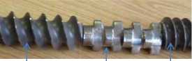
 conveyor kneading